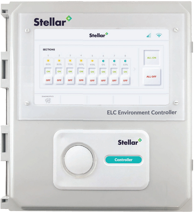
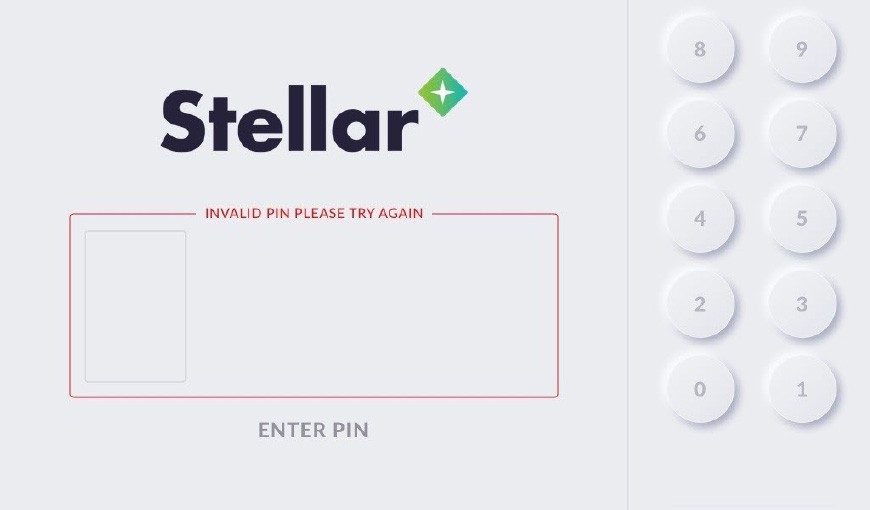
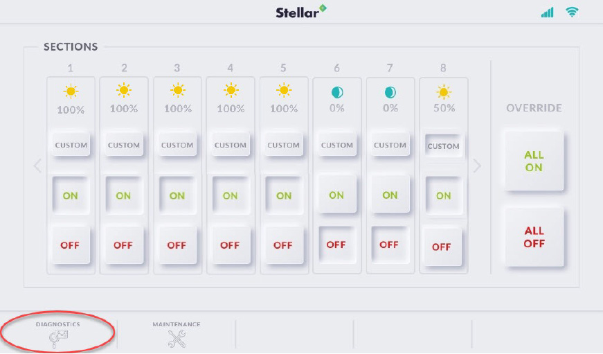
Product Installation Instructions

LED SMART LIGHT | STELLAR ENERGY MANAGEMENT

Touchscreen User Manual

These instructions will show you phase five of how to install a stellar light package inside an innovative Sprung Structure. In this phase of installation you will learn how to program the touchscreen for the AC Communicator
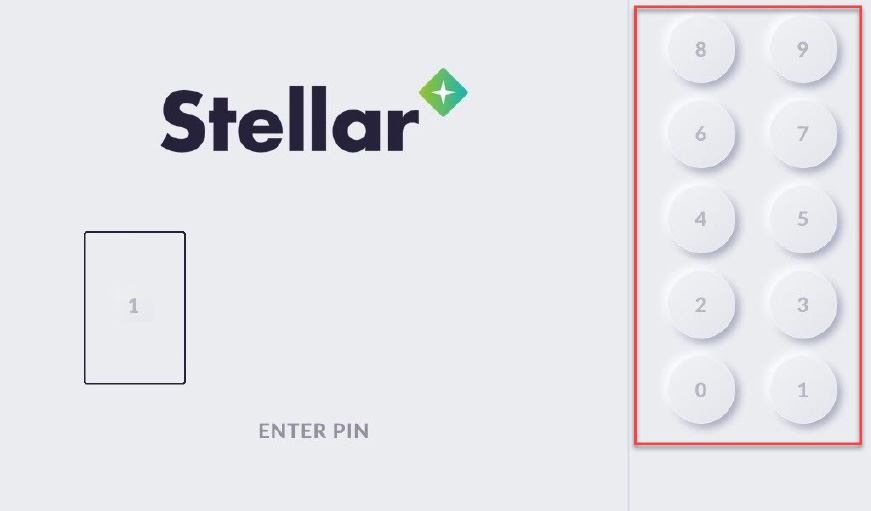
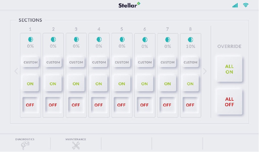
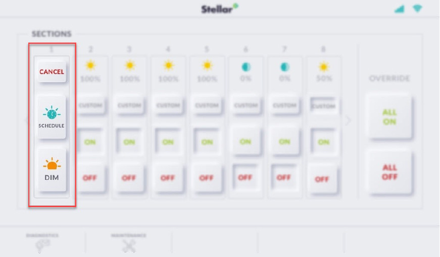
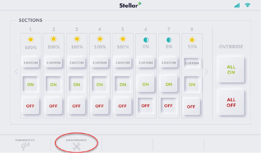
The Stellar Environmental Controller is a user friendly interface that coordinates luminaires, sensors and other sub-controllers. Records real time data allowing for system adjustments to ensure optimal energy use.

1

Pre-Home or Introduction Screen

A

This screen may be as shown below or may be customized to user specifications. The software and touch screen versions being used will be displayed in the lower right corner. Touch the screen anywhere to continue to the next screen.

2

Login Screen

A

The login screen allows you to enter a security pin before accessing control to the system.

B

Select a 4-digit PIN by pressing the round number
buttons on the right side of the screen.

C

If an incorrect digit is pressed, simply press the “CLEAR” button to re-select the correct digits.

D

When all four digits have been selected, press the “ENTER” button displayed beneath the pin display boxes to enter the PIN.

Note: The “Enter” button will not be active until all four digits of the
pin are selected.

E

If the wrong PIN is entered, the screen will display a red outline around the PIN display boxes and the text “INVALID PIN PLEASE
TRY AGAIN”. To attempt another login, re-select the digits of your PIN and press the “ENTER” button.

F

If the entered PIN is a correct security match, the screen will change to the Main Control Screen.

3

Main Control Screen

A

The Main Control Screen provides a dashboard display of each controlled lighting area. This screen is where most of the control functions are initiated.

B

Under the box titled “SECTIONS” there are columns with a number or letter on the top. This section number or letter designates a group of controlled lights in a physical location. Each section is unique and the lights grouped in each section are determined by the installation plan for each system. For example, if a customer were using the Stellar system in a production
facility one section may control the lights in a welding and fabrication bay. Another section may control lighting in walkways and general work areas. Lighting running down individual pallet racking rows may each be controlled by other sections as well. Each of these sections will be designated by a number or letter at the top of the section column. See section numbers in the red box below:

C

Each section column has a status icon and dimmer percentage representing the current status of each section. Below are some examples of the section status icons that you may see on the section columns.

D

Each section also has an “ON” button. When the “ON” button is pressed it will power the section and a corresponding icon will show the status of the section as powered. The “ON” button will be depressed if the section is powered in full or partially dimmed. The “ON” section buttons shown in the picture below shows
sections 1-5 are 100% powered, sections 5-6 are off, and section 8 is dimmed.

E

Each section column has a “OFF” button that will turn power to the section off. If the section is powered, the “OFF” button will appear un-pressed. If the “OFF” button is pressed, it will turn off power to the section and appear depressed. The corresponding 0% icon will appear above on the section column. In the image above sections 5&6 are unpowered, with the “OFF” button depressed.

F

Each section column has a “CUSTOM” button that
allows dimming and scheduling options. When the “CUSTOM” button is pressed, a dialog box appears in place of the section column allowing several
options. See the custom pop-up box in the red box below:

G

Each section column has a “OFF” button that will turn power to the section off. If the section is powered, the “OFF” button will appear un-pressed. If the “OFF” button is pressed, it will turn off power to the section and appear depressed. The corresponding 0% icon will appear above on the section column. In the image above sections 5&6 are unpowered, with the “OFF” button depressed.

H

If the “DIM” button is depressed, a pop-up slider box will appear allowing the desired dim level to be selected. Note the depressed “DIM” button in the lower left and the dimmer slider pop- up on the right of the image below.

I

If the “Cancel” button is depressed the system will return to the “Main Control” screen.

J

The ELC Touch also allows the user to override the current state of ALL sections using the “ALL ON” and “ALL OFF” buttons located to the right of the section columns. See the override buttons highlighted in the red box below:

K

When either one of the
override buttons are pressed a confirmation dialog box is opened to make sure the entire system is not accidentally turned on or off.

L

The Diagnostics button on the lower left side of the screen will change the screen to the Diagnostics
page.

M

The Maintenance button on the lower left side of the screen will change the screen to the Maintenance page.

N

If your system has more than 8 sections, the arrow keys located on both sides of the section columns will be active. Press the right arrow key to display the sections in ascending order. Press
the left arrow key to display the sections in descending order. Arrow keys will only be active (green colored) when there are additional sections available to display.

O

The Mesh and Cell Icons are located at the top right of the control screen. These icons indicate the status of Mesh and Cell signals to the system.

4

The Diagnostic Screen

A

The diagnostic screen displays a real-time view of up to 75 sections at one time. It shows number of transmissions sent and received, and it shows the percentage of transmissions that were successful.

5

Maintenance Screen

A

The Maintenance Screen allows access to several important functions. See the buttons featured in the Maintenance screen below:

B

The Screen Brightness button will bring up a page where the brightness on the screen can be viewed and adjusted. Press the positive (+) and negative (-) buttons to adjust the brightness up or down until the desired level is reached. Once the desired level is reached, the “APPLY” button can be pressed. Press the “X”
in the top right of the box to return to the Maintenance screen.

C

The Screensaver button allows screensaver settings to be viewed and adjusted. Press the positive (+) and negative (-) buttons to adjust the number of minutes before the screen saver comes on up or down until the desired level is reached. Once the desired level is reached, the “APPLY” button can be pressed. Press the “X”
in the top right of the box to return to the Maintenance screen. Note: To turn the screensaver function off, set the number of minutes to “0”.

D

The SET DATE/ TIME button allows the system
time to be set. Pushing the SET DATE/TIME button brings up a dialog box that allows you to set the time and date.

Download Phase 3 Installation Instructions

Click to view PDF Instructions For Phase 3

Click to view FULL PDF Instructions

These instructions will show you phase one of how to install a stellar light package inside an innovative Sprung Structure. In this phase of installation you will:

  Install the AC Line Communicator
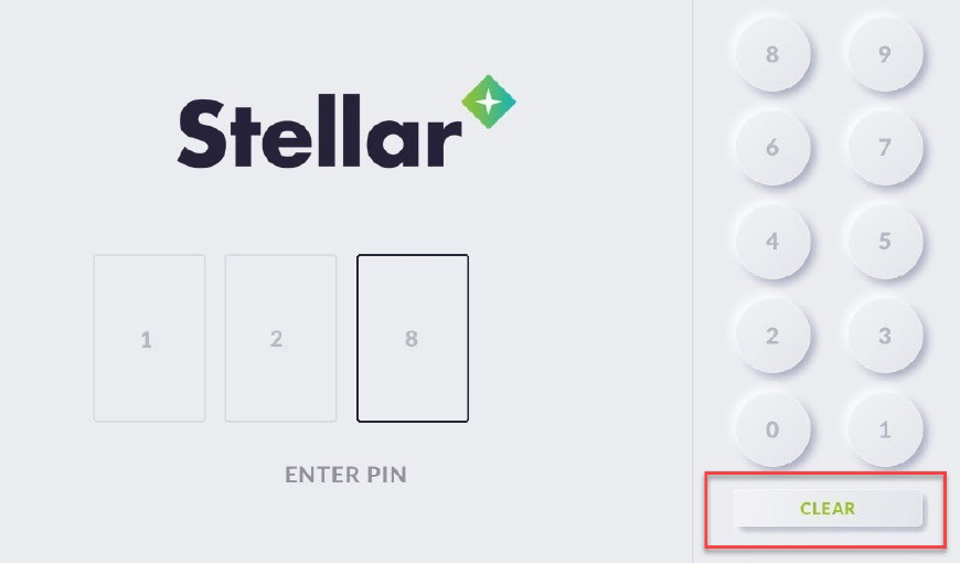
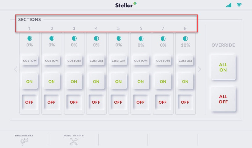
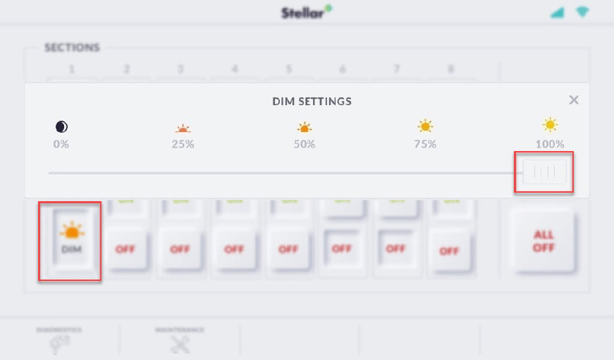
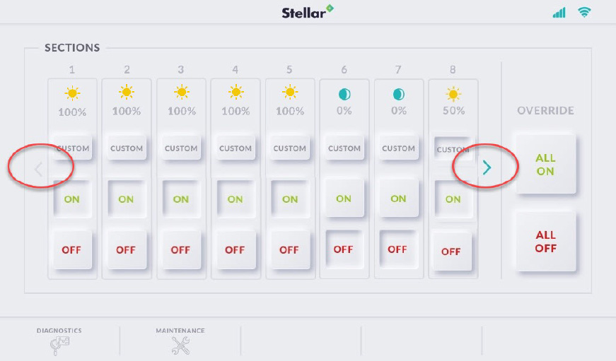
  Cover the Quick Connect access point
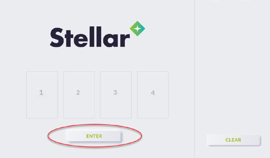
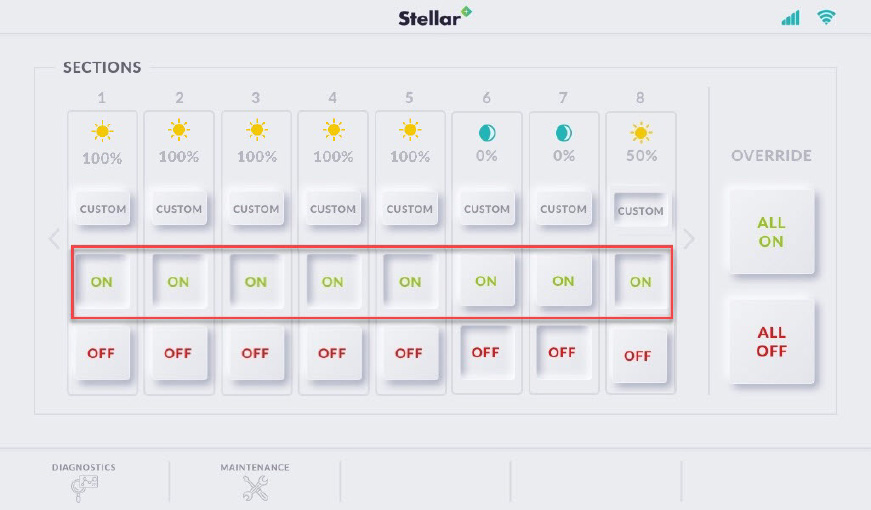
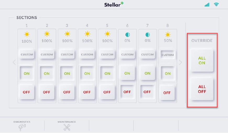
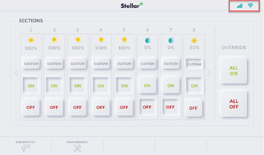
  Connect the power cable