Phase 1a Installation Instructions With AC Line Controller
These instructions will show you phase one of how to install a stellar light package inside an innovative Sprung Structure. In this phase of installation you will:
Install light boxes with AC Line Communicator on each Sprung beam
run flex conduit to each light box
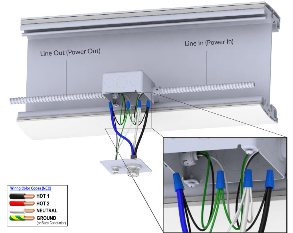
connect the wires of the light connector inside each light box
secure the connector cover plate for each box
READ AND FOLLOW ALL SAFETY INSTRUCTIONS!
Before installing, servicing, or performing routine maintenance, follow these general precautions.
Electrical Wiring Installation should be performed by a qualified licensed electrician.
Maintenance of the luminaires should be performed by person(s) familiar with the luminaires’ construction and operation and any hazards involved.
It will occasionally be necessary to clean the outside of the refractor/lens.
Frequency of cleaning will depend on ambient dirt level and minimum light output which is acceptable to user. Lens should be washed with a damp cloth of warm water and any mild, non-abrasive household detergent, wiped with clean water and wiped dry.
Recycle: For information on how to recycle LED electronic products, please visit www.epa.gov.
These instructions may not cover all details, risks or install variations in connection with installation, operation, or maintenance. Should further information be desired, or should particular problems arise which are not covered sufficiently for the purchaser’s or owner’s purposes, these matters should be referred to Stellar Smart Energy Solutions, LLC.
Prior to Installation–Read carefully before installing light fixtures. If you do not understand these instructions, please contact your local Stellar Smart Energy Solutions, LLC distributor before installing.
Before installing this fixture or doing any maintenance, make sure to turn off the power supply at the circuit breaker or fuse box.
Do not handle energized module with wet hands or when standing on wet or damp surfaces, or in water.
Check to make sure that all the fixture connections have been properly made and the fixture is grounded to avoid potential electrical shocks.
Product must be installed in accordance with NEC or your local electrical code. If you are not familiar with these codes and requirements, consult a qualified electrician.
WARNING – Risk of Electric Shock. Maximum connected load with a single power supply shall not exceed maximum ampacity rating of #18 AWG through-wire conductors. Avoid handling LEDs directly. Not intended for use in environments containing airborne corrosive agents such as chemical solvents, cleaners, or cutting fluids
DELIVERY: Upon receipt of fixture and accessories, inspect for any freight damage. All damage should be reported to the delivery carrier. Compare the catalog description listed on the packing slip with the fixture label to be sure you have received the correct merchandise.
Electrician INSTRUCTIONS!
Follow specific building lighting plans for installation location of each item.
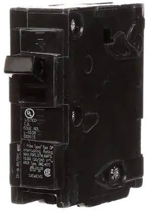
20 amp minimum circuits are required for Stellar Smart Lighting Systems. A 20 or 30 AMP breaker should be used based on the amount of current for the designed load.
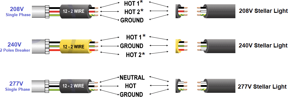
208VAC, 240VAC and 277VAC are the three voltages used. Each Stellar lighting is configured for ONE of these voltage, please ensure that the voltage provided and the Stellar Light match. The specific voltage can be found on the Safety label located on the light.
All wire runs and AWGs need to follow electrical code.
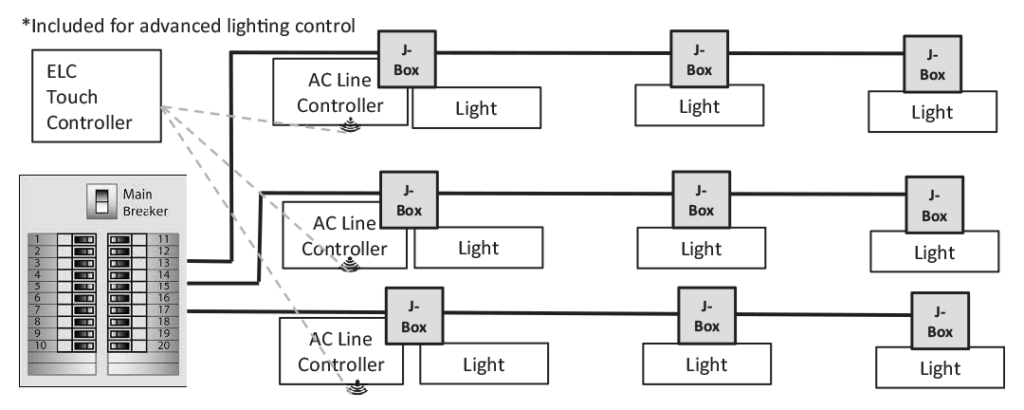
Stellar Lighting Control Electrical Schematic
(OPTIONAL)
In order to communicate to each light, each circuit needs an “AC Line Communicator” installed before the first light.
Install AC Line Communicator close to the Main Breaker as the first Light box in the circuit refer to Step 1A.
PARTS AND HARDWARE PROVIDED:
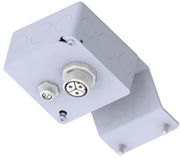
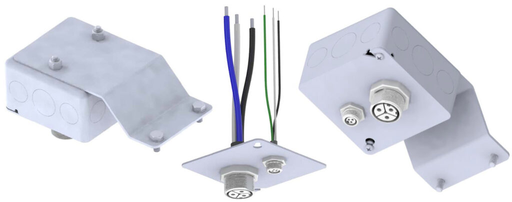
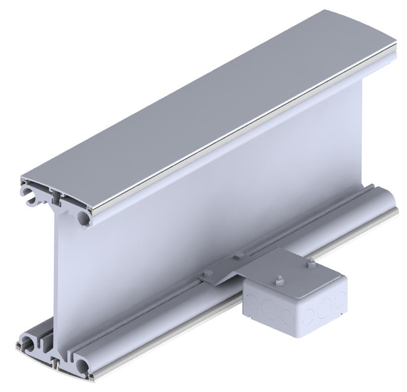
AC Line Communicator & Light Box Assembly
1/4”-20 x 5/8” Bolts and 1/4” Lock Washers packaged separately
ELECTRICIAN SUPPLIED PARTS AND EQUIPMENT:
(May not be a complete list)
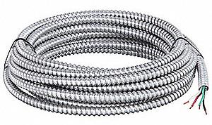
3/8 Flexible aluminum conduit
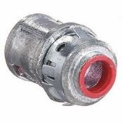
Push-In Fitting for 3/8 flex conduit
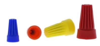
Wire nuts to code
Example of clamps to attach flex conduit to Sprung beam (hole must fit 1/4”-20 bolt)
Use 1/4”-20 X 5/8” hex bolts to attach flex cable clamps onto Sprung beam
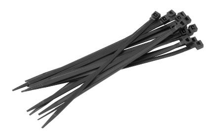
Zip ties
Breaker
ELECTRICIAN INSTALLATION INSTRUCTIONS
Install AC Line Communicator & Light Box Assembly (4×4” J-Box 2 1/8” deep). Follow building lighting plans for location.
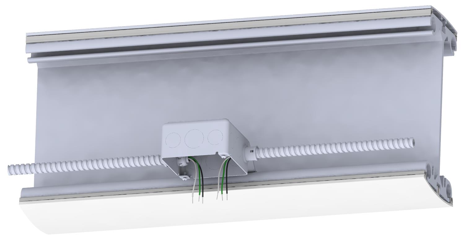
1/4″-20 X 5/8″ Hex Bolt
.260” ID X .487” OD Split Lock Washer
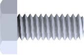
2. Run flexible metal conduit (size according to code) to all 4×4” J-Boxes.
Light Box (4×4” J-Box 2 1/8” deep)
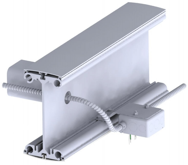
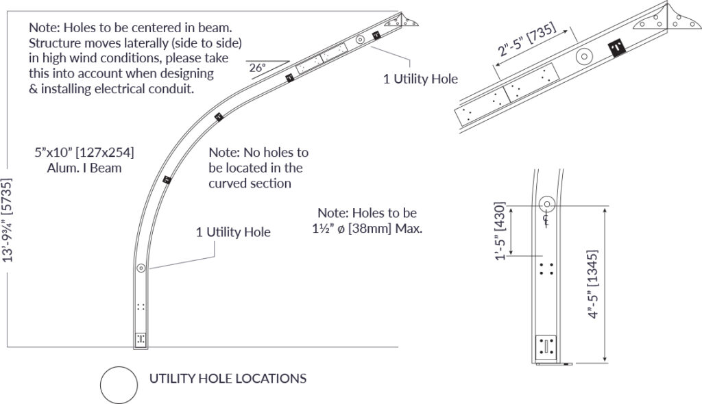
3. Use pre-drilled Utility Holes to run flex conduit between Sprung beams. Zip tie flex conduit to spreader posts.
Zip tie flex conduit to spreader posts
Utility Hole drawing example from Sprung:
4. Connect wires from Light Plate Assembly to AC Line Communicator & Light Box (4”X4” J-Box 2 1/8” deep).
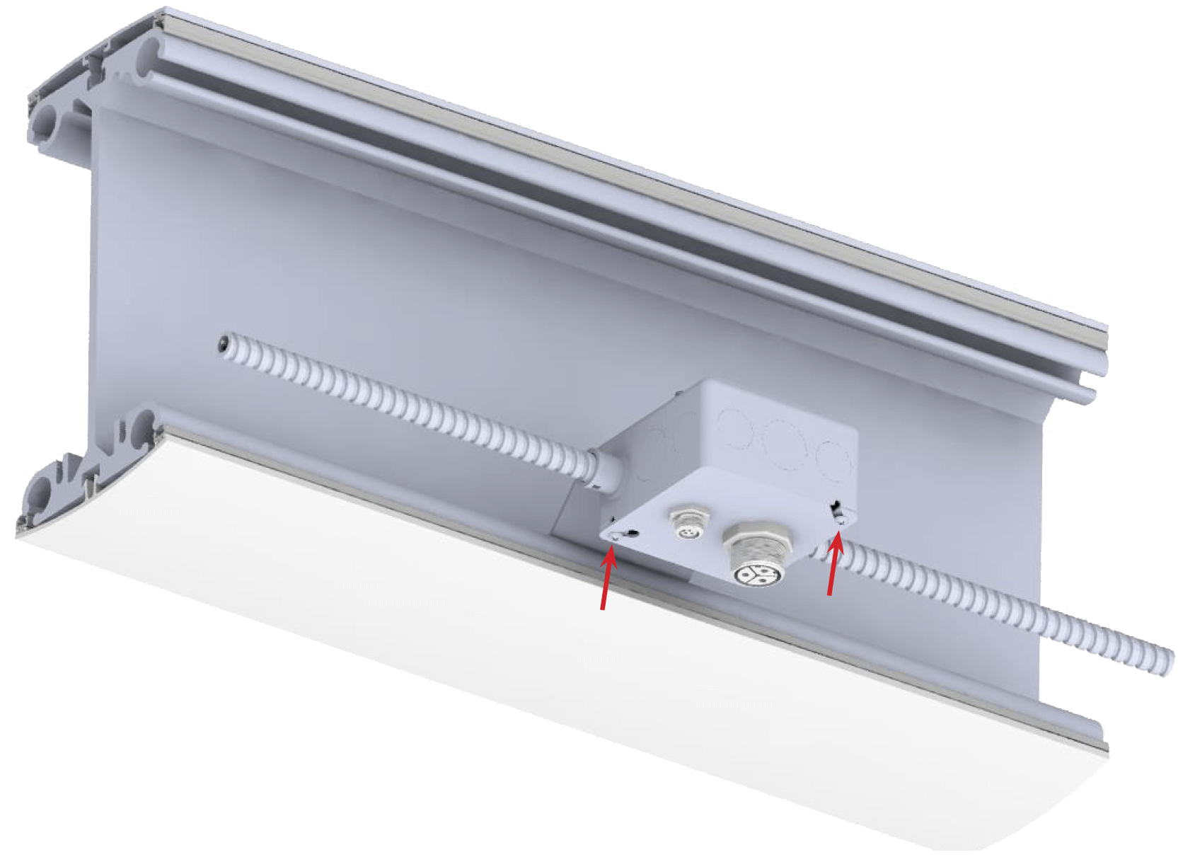
5. Attach AC Communicator Line & Light Box Cover Plate Assembly to AC Line Communicator & Light Box (4×4” J-Box 2 1/8” deep) using 2 Phillips head screws provided with J-Box.
Phillips Head Screws
ADDITIONAL NOTICES:
FCC NOTICE: This device complies with Part 15 of the FCC Rules. Operation is subject to the following two conditions: (1) this device may not cause harmful interference, and (2) this device must accept any interference received, including interference that may cause undesired operation. Any Changes or modifications not expressly approved by the party responsible for compliance could void the user’s authority to operate the device.
CAUTION: PRODUCT DAMAGE RISKS
Never connect components while lights are on or connected to power source.
Do not mount or support these fixtures in a manner that can cut the outer jacket or damage wire insulation.
Never connect an LED product directly to a dimmer switch. LED fixtures must be powered directly off a switched circuit and use Stellar Smart Lighting controls and ELC components.
Unless individual product specifications state otherwise, do not restrict fixture ventilation. Allow for 2 inches of airspace around fixture. Avoid covering LED fixtures with insulation, foam, or other material that will prevent convection or conduction cooling.
Unless individual product specifications state otherwise, do not exceed the fixture’s maximum ambient temperature of 40 C/104 F.
Only use the fixture in its intended location.
LED products are Polarity Sensitive. Ensure proper polarity before installation.
Electrostatic Discharge (ESD) can damage LED fixtures. Personal grounding equipment must be worn during all installation or servicing of the unit.
Do not touch internal LED and electrical components as this can cause ESD, shorten lamp life, or alter performance.
Some components inside the fixture may not be serviceable. In the unlikely event your unit may require service, stop using the unit immediately and contact Stellar customer service for assistance.
Always read the fixture’s complete installation instructions prior to installation for any additional fixture-specific warnings.