These instructions will show you phase two of how to install a stellar light package inside an innovative Sprung Structure. In this phase of installation you will:

Assemble the light brackets
Drill holes for T-Bolts
Secure the light brackets to the Sprung beams
WARNING – Risk of Electric Shock. Maximum connected load with a single power supply shall not exceed maximum ampacity rating of #18 AWG through-wire conductors. Avoid handling LEDs directly. Not intended for use in environments containing airborne corrosive agents such as chemical solvents, cleaners, or cutting fluids
DELIVERY: Upon receipt of fixture and accessories, inspect for any freight damage. All damage should be reported to the delivery carrier. Compare the catalog description listed on the packing slip with the fixture label to be sure you have received the correct merchandise.
Follow specific building lighting plans for installation location of each item.
20 amp minimum circuits are required for Stellar Smart Lighting Systems. A 20 or 30 AMP breaker should be used based on the amount of current for the designed load.
208VAC, 240VAC and 277VAC are the three voltages used. Each Stellar lighting is configured for ONE of these voltage, please ensure that the voltage provided and the Stellar Light match. The specific voltage can be found on the Safety label located on the light.
All wire runs and AWGs need to follow electrical code.
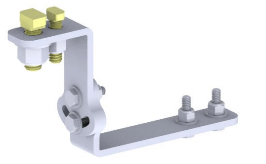
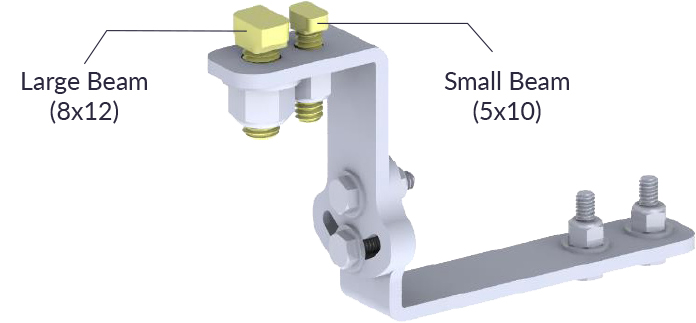
Large Beam – Hardware (1/2”)
Small & Medium Beam – Hardware (3/8”)
Large Beam – Hardware (1/2”)
Small & Medium Beam – Hardware (3/8”)
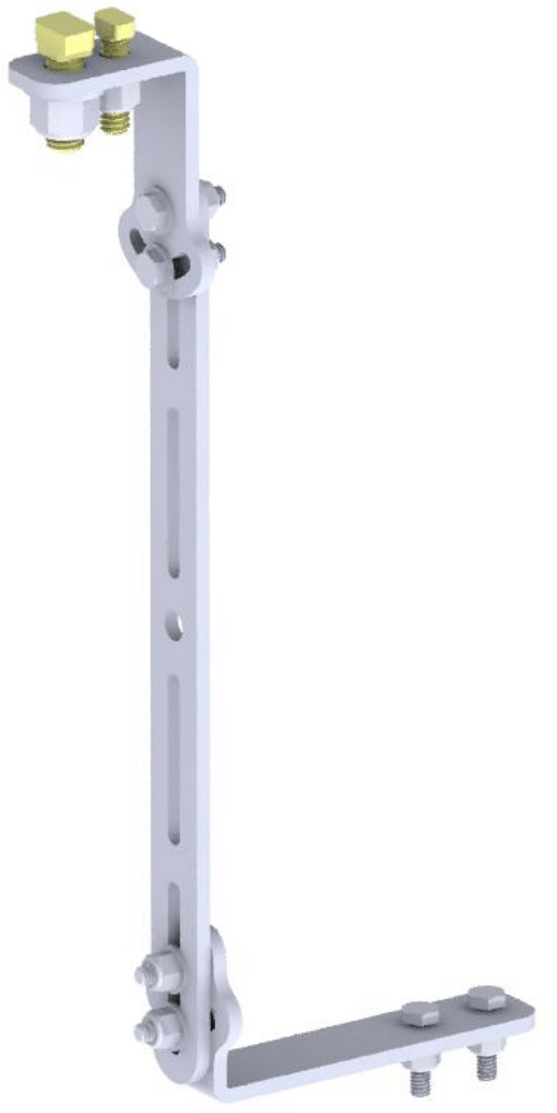
Extension Bracket (Optional, must be ordered separate)
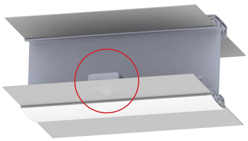
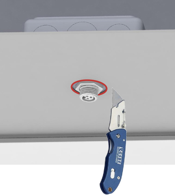
2. Use a box knife to carefully cut around Quick Connects. CUT AS CLOSE AS YOU CAN TO EXPOSE THE QUICK CONNECT ACCESS POINT ONLY.
3. Drill 2 holes in Sprung Interior PVC Cap to install Light assembly (hole distance will vary depending on light). Small & Medium Sprung Beams: Drill 3/4” holes; Large Sprung Beams: Drill 1” holes
1. Mark the location of the hanging bracket in the center of the interior PVC cap.
2. Using the correct hole saw drill a hole through the interior plastic cap making certain not to bore into the beam itself. [ ¾” hole saw for 5”x10” beams or 1” hole saw for 8”x12” beams ]
3. Remove the excess cap material, cleaning the hole of debris.
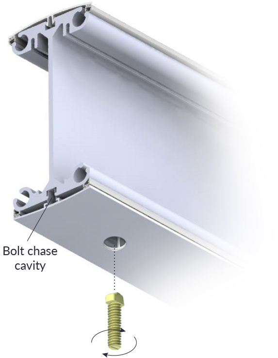
4. Position a T-bolt into the aluminum beams bolt chase.
5. Turn the T-bolt clockwise 90 degrees and lock it into the bolt chase.
Note: that the indicator line on the end of the T-bolt running perpendicular to the length of the beam confirms that it is locked in place.
4. Next, whether you are using the standard or indirect light bracket, you will attach the light bracket assembly to the Sprung beam by sliding the bracket onto the T-bolt that is sticking out of the beam and then fixing it with the accompanying nut. Please note the hole distance will vary depending on the light you are installing.
FCC NOTICE: This device complies with Part 15 of the FCC Rules. Operation is subject to the following two conditions: (1) this device may not cause harmful interference, and (2) this device must accept any interference received, including interference that may cause undesired operation. Any Changes or modifications not expressly approved by the party responsible for compliance could void the user’s authority to operate the device.
Stellar Smart Energy Solutions
8774 N Cedar Fork Cir
Eagle Mountain, UT 84005
801-332-9373